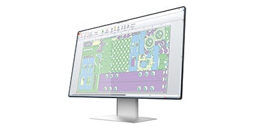
Scribing with ProNest
ProNest makes scribing easy with intelligent tool path application and seamless programming
by
What is scribing?
Marking, etching, scribing – there are many terms to describe the process of adding marks to a metal surface. Lines or points can be used to guide cutting, drilling, or bending. Letters and numbers can be used for tracking purposes. For example, part name, customer name, stock number, heat number, or other reference ID.
Scribing with plasma
While ProNest® also supports the more advanced powder marking process, as well as laser and waterjet scribing, we’ll focus here on the low-power plasma “scribing” process. If your machine supports scribing, then your ProNest machine setup file will include this capability, allowing you to output code with scribing applied to the job. In any case, it’s straightforward to set up, process, or program the job in ProNest.
How to scribe in ProNest
The first thing that differentiates ProNest scribing from other software products in the same category is just how automatic and straightforward the process is. While other products require discrete programming and processing for scribing operations, ProNest does not.
To set up scribing in ProNest, you need to map your CAD layers to your scribing process, and sometimes that is done for you. It’s that easy. When doing this, use ProNest’s easy-to-navigate Settings menu, and under Importing Parts, assign layer aliases to your scribe cut process. An alias is simply a layer name in the CAD file that ProNest recognizes as the scribe layer. Multiple aliases can be used when drawings come from multiple companies or departments with different naming practices. These can be separated using commas, so if you have a customer using layer ‘2’ and another using ‘Scribe’, you can easily reflect this in the settings.
Sequencing is handled automatically, with a simple checkbox controlling whether scribing is processed first (Punch/Scribe first).
At this point, you may be wondering how to add part names in ProNest. It’s easy! When editing a part using the Advanced Edit feature, click the A icon, then click anywhere on the part. You’ll see text defaults to the part name, but under the Text drop-down in the Properties window, you can choose from a range of common text properties, such as Date, Customer, Revision, etc. You can also override this text if necessary.
Once satisfied with your text and its position on the part, return to Nesting and nest your parts.
Scribing with variables
Variables are another nice feature to leverage. Variables can be used in scribe text, providing a convenient way of adding standard information (such as heat number, part name, material, etc.) to your parts for marking. Variables, which act as placeholders for actual values, can be added in Advanced Edit in ProNest or included as text in the CAD file and automatically added to the part.

Adding scribe variables can be done in CAD, so your parts are ready to go once you begin nesting, or you can add them manually in ProNest’s advanced edit screen. In either case, the ProNest help menu provides a list of variables that you can choose from, including:
-
PartName
-
Customer
-
Revision
-
SequenceNo
-
QtyRequired
-
QtyNested
-
Material
-
Thickness
-
Grade
-
And many more
You can also create scribe text that uses variables with mathematical equations. This may be useful for applying serial numbers or other data to parts or plates. For example, every part on a nest is marked with a sequence number. The first digit is the nest number, and the last digits represent the cut sequence order on that nest.
The results for parts on Nest 1 could look like:

Related products
ProNest 2025
ProNest® CAD/CAM part nesting software for advanced mechanized cutting is designed to supercharge your cutting operation, helping you achieve greater automation, efficiency, and profitability.
ProNest 2019 LTS
ProNest® LTS software has been discontinued in favor of Hypertherm’s other industry leading nesting software products (ProNest®, and ProNest® LT). Hypertherm will continue to provide technical support.